MX350 Controller

ATS MX Contactor
ATS MX Contactor (9)
-
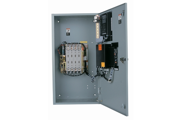
CTX Series Automatic Transfer Switch
-
MX150 Microprocessor Controller
-
MX250 Microprocessor Controller
-
-
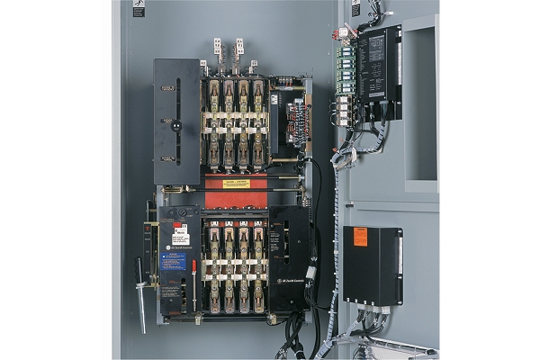
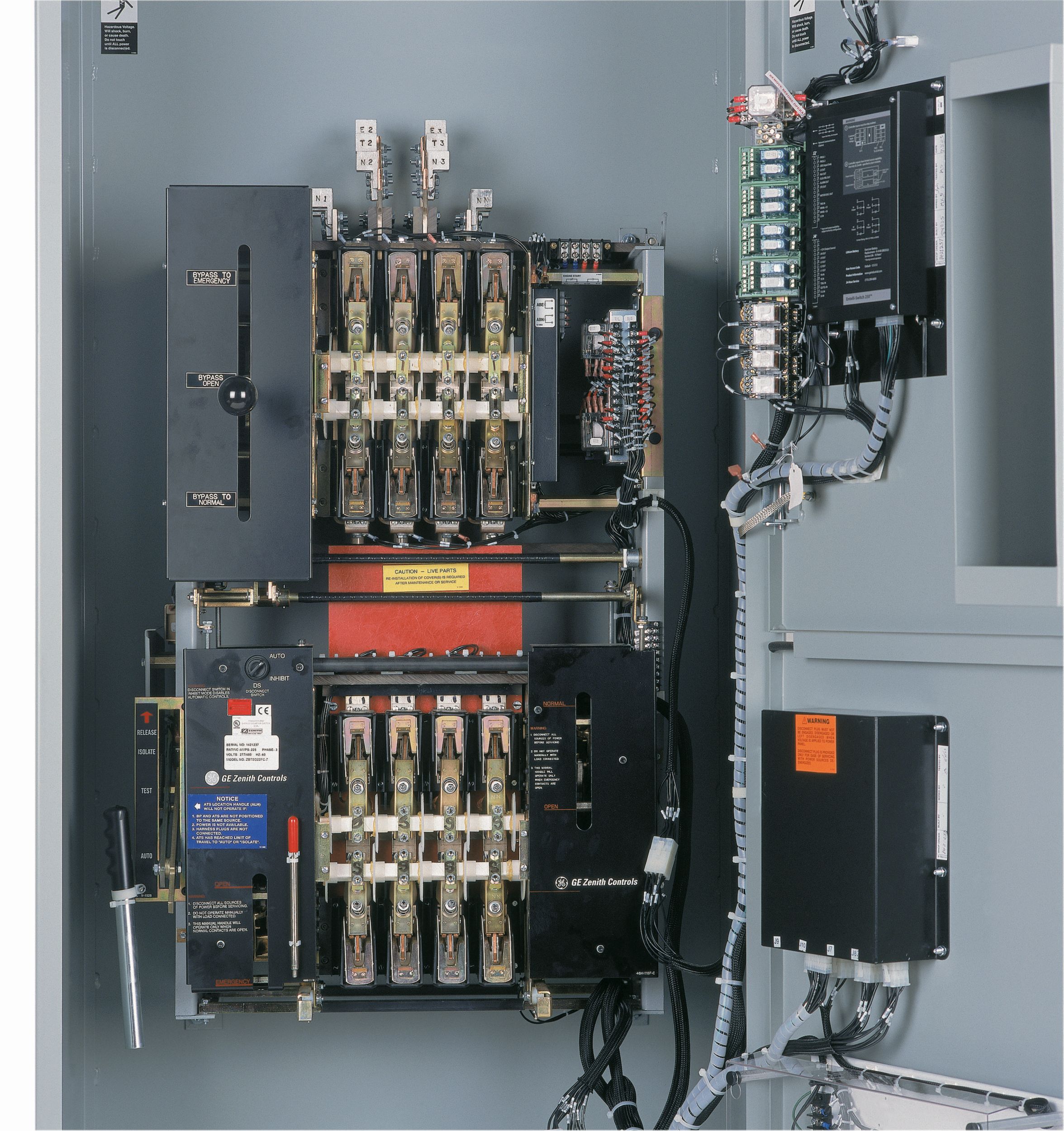
CTS Series Automatic Transfer Switch
-
CTSM and CTGM Series Manual Transfer Switches
-
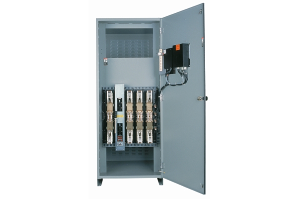
CTE Series Automatic Transfer Switch
-
-
Overview
The MX350 controller is specifically designed for low voltage Automatic Transfer Switch (ATS) applications. The flexible control and communications options are ideal for any application. Integrated push buttons, graphical controls and LED indicators reduce external components and wiring in addition to providing local control and access to system information. Multiple communication protocols allow simple integration into monitoring and control systems.
Features and Benefits
- Dual Communications
Built-in RS-485 serial and 10/100 base-T Ethernet
Open protocols - Modbus RTU and Modbus TCP - Available to support Open, Closed and Delayed Transition
- Small footprint
- Graphical control panel
- Multiple communication protocols
- ¼ inch VGA color graphical display with embedded HELP menus
- Status LED's indicating:
ALARM - indicating a problem with the ATS or a user configured alarm condition is active
TD DELAY - indicating the controller is timing before taking the next control action
XFER INHIBIT - indicating the controller will not transfer to the other source without operator intervention
SOURCE 1(S1) AVAILABLE LED - indicating power is present per user setpoints
SOURCE 2 (S2) AVAILABLE LED - indicating power is present per user setpoints
SOURCE 1 (S1) STATUS LED - indicating load is connected to S1 power
SOURCE 2 (S2) STATUS LED - indicating load is connected to S2 power - User-Configurable setpoints for inputs and Outputs
- Field modification of control features
- Plant exerciser clock for 1 day, 1 week, 14 days, 28 days or 365 days. The time base of 365 days permits up to 24 events to be scheduled and the other time bases permit up to 24 events.
- SYSTEM TESTS
Fast Test - test with load, no time delays
Transfer Load - test with load with time delays
No Transfer - test without load, generator start only - Controller Power Supply utilizing the Universal Transformer Assembly (UTA) - provides 170Vdc to the controller and 24Vdc ungrounded to the power relays. The UTA also provides line voltages from 120Vac to 600Vac via an internal six position jumper array, 120Vac UPS input and 24Vdc input battery options.
- Dual processor based with dedicated processor for high speed Serial or Ethernet connections
- All signal in / out relays are isolated via DIN Mounted relay / terminal blocks
- Elevator pre-signal contacts
- Power quality metering
- Elevator pre-signal
Technical Summary
- Rating Range
- Switch Dependent
- Transfer Type
- Application Dependent
- Switch Type
- Application Dependent
Controller Specifications
- Source Sensing
- 120 - 690 VAC +/- 1% of nominal voltage (+/- .05 Hz, +/-.5 A)
- Control Power
- 120 VAC
- Communications Interface - Optional
- Serial RS-485 upt to 115.2 Kbps or TCP/IP (10/100 base-T)
- Undervoltage Dropout for Source 1 and Source 2
- 75-99% of nominal
- Undervoltage Restore for Source 1 and Source 2
- 85-100% of nominal
- Underfrequency Dropout for Source 1 and Source 2
- 45 - 59.9 Hz
- Underfrequency Restore for Source 1 and Source 2
- 45 - 59.5 Hz
- Overvoltage Dropout for Source 1 and Source 2
- 105 - 110% of nominal
- Overvoltage Restore for Source 1 and Source 2
- 103 - 108% of nominal
- Overfrequency Dropout for Source 1 and Source 2
- 50.1 - 63 Hz
- Overfrequency Restore for Source 1 and Source 2
- 50 - 62.9 Hz
- Voltage Unbalance on Dropout for Source 1 and Source 2
- 5 to 20% of nominal
- Voltage Unbalance for Restore for Source 1 and Source 2
- 4 to 19% of nominal
- Load Control Relay Contacts (1)
- rated for 10A @ 24VDC or 120VAC
- Load Control Relay Contacts (2)
- 0-259 minutes
- Delay for Engine Cool Down (U)
- 0-60 minutes
- Delay Transfer to Nonpreferred Source (W)
- 0-5 minutes
- Delay NeutralTransition Time Delays (DT,DW)
- 0-10 minutes
- Storage Temperature
- (-40˚C - 90˚C )
- Operating Temperature Ambient
- (-20˚C to 50˚C)
Standard/Optional Features
Standard Equipment:
-
- Status Leds For:
-
- Transfer Inhibit
- Active Alarms
- Source 1 and 2 Availablity
- Source 1 and 2 Connected
- Time Delay Active
-
- Graphical Display:
-
- Color graphical display with USB Calibration/programming port and Embedded Help
- Displays 256 time-tagged events with 1 ms resolution
- Monitors over/under frequency, voltage conditions, frequency imbalance, and phase rotation
- Provided detailed outage,test,and diagnostic reports
-
- Ranges Of Controls / Metering:
-
- Programmable generator exerciser
- Synchroscope
- Contacts for Source 1 and Source 2 position indication as well as remote load test signals, and engine start delay
- Source 1 and Source 2 In-phase monitor
- Neutral, Engine Start, and Engine stop time delay timers
-
- Testing And Certification
-
- Conforms to EN 60947-1, EN 60947-6-1, EN 60255-26 (EN 50263), EN 5502 / CISPR22 / EN 61000-6-2 / EN 61000-6-4
- Tested in accordance with:
IEC 60068-2-30
IEC 60068-2-1
IEC 60068-2-2
IEC 60255-22-1
IEC 60255-22-2
IEC 60255-22-3
IEC 60255-22-4
IEC 60255-22-5
IEC 60255-22-6
IEC 60255-25
IEC 60529; IP54 (front),IP20(back)
IEC 61000-4-11 - Quality System:
Manufactured under an ISO 9001 Registered Program
Optional Equipment:
-
- Option Package A:
-
- Four (4) programmable inputs and four (4) outputs assignable to additional ATS features
- Expanded diagnostics, high-speed 256 event capture, 365 days
- Monitoring Software (local or remote), USB interface for uploading and downloading setup parameters
- Full function ATS control with full sensing and control capabilities
- Full complement of programmable ATS control switches AUTO / MAN, Preferred Source selector,Commit / No Commit Xfer, Transition Mode Select for Closed Transition switch models)
-
- Option Package B:
-
- Waveform capture, ten (10) channels, up to 256 cycles each sixteen (16) samples / sec.
- Ten (10) customer programmable digital and ten (10)analog alarms.
- Includes Option Package A features, plus
- Auto Load Shed with voltage, frequency and kW triggers.
- Twenty (20) channel data logger, customer configurable sample period from one (1) cycle to sixty (60) minutes.
-
- Option Package C:
-
- Includes Option B features, plus
- Four (4) additional inputs and outputs (totaling eight (8) in & eight (8) out)
-
- Option Package D:
-
- Customized user control logic
- Includes Option Package C features, plus
- Four (4) additional inputs and outputs (totaling twelve (12) in & twelve (12) out)
-
- Option Package M:
-
- Configuration for Manual Operation only (Non-Automatic)

Take The Virtual Product Tour To Explore The Features And Benefits of the MX350 Controller
See how MX350 Controller compares against frequently compared products